
QAP & EHS
General Quality Assurance and Quality Control Plan for installation of bored cast-in-situ piles
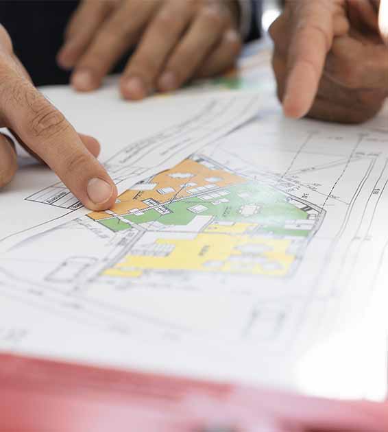
Once the design is completed and Good for Construction pile layout drawing is received at site for installation, a detailed work program is prepared, taking into consideration the major project milestones. All templates and quality check formats are also prepared and kept ready.
The following are the major steps involved in installation of bored cast in-situ concrete piles.
Preparation of Working Zone
Working zone will be cleaned and necessary level will be taken and bench marked. Sufficient water and lighting arrangements will be done. Required nos. of bentonite circulation tanks will be prepared.
Setting Out Pile Points
Based on the GFC drawing, the pile points are setout precisely. As per IS 2911, the maximum tolerance permissible for piles with diameter 600mm or more is 75mm or D/10, whichever is more. For single piles below columns, the tolerance shall not be more than 100mm for piles with diameter more than 600mm. For piles with diameter upto 600mm, the tolerance limit is 50mm. The set out points are marked clearly - for easy identification, and firmly - so as not to affect by any activities around. The setting out is done with Total Station or with a theodolite. However, cross checking of the points established is done before starting the piling activity. Temporary reference points (TR) are established for this purpose. All the piles are grouped in to small groups, and each group is locally measured from a temporary reference point. All these TRs are inter-connected and the distance between them, distance from them to the pile points, and distance from the base reference etc are measured and recorded, both in tabular as well as graphic form for cross checking.

Preparation of Rig Movement Plan
A layout showing the anticipated path for Rig movement is prepared based on the work program and the planned deployment of resources. The layout is prepared in such a way that easy maneuvering of all the rigs is possible without causing any disturbance to the operation of other rigs. This will give the team a clear picture on planning the next day’s work, and also to make preparations for the piles which need to be attended to next.
Boring Activity
The rig is next shifted and positioned over the established pile point. The point is cross checked with other reference points to ensure accuracy. The diameter of the cutting tool is checked, this shall not be less than the required pile diameter by more than 75mm. After shifting rig to position, the casing is driven keeping the pile point at the center. The depth to which the casing is driven is decided based on various factors including the nature of the soil. The steel casing can ideally be driven to a depth of at least 1m below the ground level to take lateral loads and movements at site. Permanent steel casing called liners can also be provided for loose soils as per consultant’s advice. Before starting the boring activity, the density of the bentonite slurry is checked. The density of the slurry is checked intermittently during the boring activity also, to ensure that the density is within the permissible level. Care to be taken for ensuring that the piles are driven straight. Unbelievably, In spite of the fact that boring is done with freely falling chisel; piles do have a possibility of following inclined paths. Once started, it is advisable to continue and finish the boring activity in minimum possible time, without any substantial stoppage in between. Boring is stopped once the bore has attained the termination criteria as indicated in the structural report based on the soil test report. The criteria would be either the length of the pile incase of friction piles, and characteristics of substrata in case of end bearing or combination piles. In either case, the soil strata characteristics at the bottom of the pile at termination level are closely monitored. It is advisable to conduct penetration tests to determine ‘N’ value of the founding strata. Also, soil / rock sample are collected from the founding strata, and are kept for future reference. It is also advisable to collect soil samples from each intermediate soil strata at the depths mentioned in the soil test report.
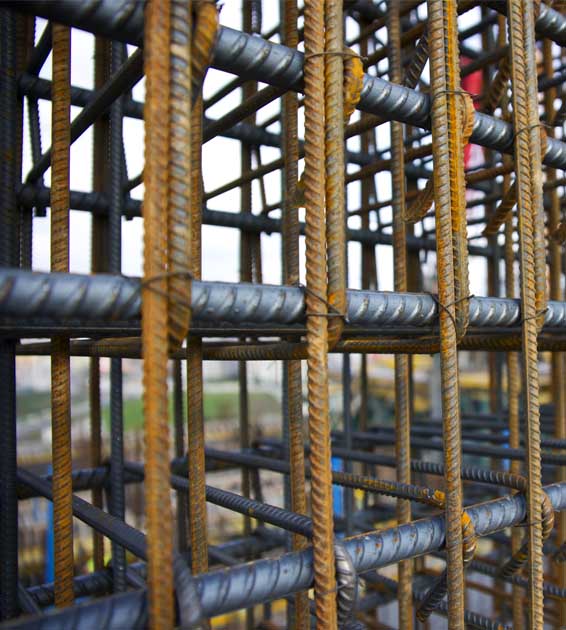
Reinforcement Cage Preparation & Lowering
Reinforcement steel cutting and bending as per BBS and Cover Blocks will be used at an interval of 2.0 M which were made well in advance and properly cured. Every stiffner and every 4th ties are welded with main bar. Cages are stacked over sal-ballah. Reinforcement cage will be lowered vertically to the bore holes after proper lap-welding.
Concreting
After confirming the pile has reached the termination level, the DMC pipes are removed from the borehole. The depth of borehole is determined preliminarily by measuring the length of the bailer pipes upon removal from the hole. Reinforcement cage is lowered vertically to the borehole, without disturbing the sides of the hole, after removing the bailer pipes. Adequate cover blocks are provided all around the cage to ensure sufficient cover. Sufficient stiffener bars also are provided to avoid sideways sway. Stirrups, stiffeners and laps are ideally welded to avoid breakage. Following this, the tremie pipes are lowered in to the borehole. The tremie pipes usually have a diameter of 200mm. The bottom of the bore hole is cleaned very carefully before starting the concreting. This is done by continuous flushing with fresh flushing mud. Consistency of flushing mud is checked and maintained, to avoid mixing of flushing mud with concrete. The bore hole is flushed for at least 30minutes prior to concreting. Sounding is done at the bore hole to precisely measure the bore depth. This measurement obtained by sounding is cross checked with the measured length of bailer pipes removed from the borehole. Before starting the concreting works, the specific gravity of flushing mud at the bottom of the bore hole is brought down to 1.2, if it is more. The tremie is lowered to the bottom of the borehole, and a hopper is connected at the top of the tremie pipe. Concrete used for pile concreting shall have a minimum slump of 150mm. The joint between hopper and tremie pipe is closed with a steel plug before the first charge. The hopper is then filled with concrete to the full capacity. Once filled, the steel plug is removed to allow the concrete to flow down and replace the bentonite slurry present in the pipe. The bottom end of the tremie pipe is always kept embedded, at least 2m, within the laid concrete so that the bentonite is replaced from bottom upwards and the concrete is not mixed with water or bentonite. Only the initially poured concrete is in contact with the bentonite slurry within the borehole. The tremie pipe remains hollow after the first charge and each subsequent charge gets deposited within the already laid concrete. Concreting is done to at least 60 – 90cm above the cutoff level to ensure good concrete for proper embedment into pile cap. If the cutoff level is at ground level, the concrete is allowed to spill over till good concrete is visible. Once started, the concreting is continued uninterrupted till the end.

Handing Over the Site
Upon successful completion of the entire job, all the machineries and infrastructures will be dismantled and removed within a week from the site and working zone will be cleaned and leveled as far as possible and will hand over the site after taking as built joint measurement. All the above stages of activity will be monitored by a group of skilled workforce at our end and necessary records will be kept in duplicate, one set will be handed over to the client’s representative and another will be in our records.